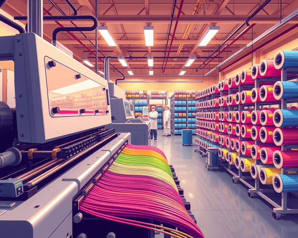
High-Speed Fiber Coloring Machine Solutions
More than 60% of FTTH lines utilize automated marking and dyeing to keep up with demand. Still, many producers miss the advantages of high-speed fiber coloring equipment. These machines increase throughput and ensure repeatable quality.
In this article, we explore industrial Fiber cable sheathing line solutions for optical fiber and textile lines. We show how a fiber coloring/dye machine fits into a draw-to-coat workflow and an FTTH line. You’ll discover how high-throughput dyeing boosts color coding, reduces manual handling, and facilitates inline proof testing.
Leading suppliers offer expert production technology training for customer teams. Along with R&D units, they adapt systems to meet specific needs. Notably, reputable companies guarantee a 100% inspection rate before shipping their products. Standard commercial practices apply, such as T/T and L/C payments.
The industry standard for warranties and logistics includes a one-year warranty from installation date. This includes parts replacement for quality defects. Buyers may incur travel and accommodation expenses for on-site service requirements. Standard packing uses PVC film for main machines and wooden cases for auxiliaries. Custom packing can be arranged upon request.
Key Takeaways
- Integrating high-speed coloring machines improves throughput and consistency across FTTH/textile lines.
- Vendors provide training, customization, and 100% pre-shipment inspection.
- Dye machine for fibers improves inline proof testing and reduces manual spool handling.
- Common payment methods include T/T and L/C; warranty typically begins at installation for one year.
- Standard packing = PVC film + wooden crates; custom packing on request.
Overview of High-Speed Fiber Coloring Systems
High-speed fiber coloring systems deliver markings or colors that are consistent, without affecting fiber strength or clarity. They run at draw/coating speeds to prevent bottlenecks. Manufacturers focus on holding color accuracy, automating quality checks, and reducing manual spool handling. This meets the needs of both the telecom and textile industries.
Defining a High-Speed Fiber Coloring Solution
A true high-speed fiber coloring machine applies colorants or inks accurately at high speeds. Precise control of width, contrast, and adhesion is maintained. That way optical loss and mechanical integrity remain intact. Features typically include solvent/UV inks, precise metering, and efficient curing for optimal results.
Key performance benchmarks: speed, accuracy, and uptime
Performance requirements depend on the application. Single-line markers can run up to 3,000 m/min. Whereas ribbon coloring aims for 1,000 m/min, with accurate color codes and low waste. Long-term repeatability, precise registration, and color stability are critical.
Higher uptime is achieved through automation, like automated spool handling and real-time testing. They reduce manual checks and spool swaps. Modular designs and predictive maintenance reduce downtime. This produces consistent production levels.
Where It’s Used: Fiber & Textile
Optical fibers use these systems for tasks such as FTTH cable marking, FTTH cable production line, telecom color coding, and ribbon marking. They integrate with draw/coating to keep flow continuous. Inline tests ensure every segment meets strength/clarity specs.
Textile industry techniques have been adapted to improve dye control, reduce waste, and save energy in fiber coloring. Lessons from yarn and fabric dyeing have led to better fluid management, automatic mix adjustments, and sustainable operations. Cross-pollination reduces time and improves quality across both sectors.
| Benchmark | Optical Fiber Example | Textile Analog |
|---|---|---|
| Top speed | Up to 3,000 m/min for single-line marking | High-speed yarn dyeing lines up to 1,000 m/min equivalent throughput |
| Accuracy | Registration within ±0.5 mm, stable color-code fidelity | Consistent color repeatability across batches |
| Uptime enablers | Automatic reel handling, inline proof testing | Automated dye dosing and closed-loop quality control |
| Integration | Seamless connection to fiber draw tower and coating lines | Integration with dyeing baths and finishing lines for minimal handling |
| Sustainability gains | Reduced scrap, solvent recovery, LED curing options | Lower water and chemical use via precision dosing |
About the Fiber Coloring Machine
Fiber coloring machines apply durable color codes to optical/industrial fibers. Precision applicators, fast curing, tension control, and smart sensors are used. This process ensures efficient production. It is designed to seamlessly integrate with existing drawing and coating lines. It also connects to inline tests and automation for streamlined flow.
Applicators deposit UV inks/liquid dyes with precision. Then, LED modules or focused UV lamps immediately harden these inks. Fibers keep moving at speed without delay. Transport guidance and tension control systems maintain the fiber’s shape while it is being marked. Pumps/filters feed from reservoirs/tanks consistently. PLC/HMI provide easy control and rapid changeovers. Sensors monitor the ink’s placement, ensuring each mark matches quality standards.
How they work together
The applicator synchronizes deposits according to fiber movement, controlled by sensors. Curing locks marks for immediate downstream handling. Sensors check intensity and registration. On error, the system flags or rejects the affected segment. Ink, speed, and curing remain synchronized to keep quality high.
Upstream/Downstream Compatibility
Modules mount behind draw towers or on secondary coating lines. Different mounting options support various fiber types. It adapts to tight-buffer or loose-tube formats. Multiple coatings/profiles are supported. Many leading suppliers, including Sumitomo, Furukawa, and Corning, provide compatible equipment. The result is seamless integration for plants.
Inline Proof Test & Automation Integration
After marking, inline proof tests validate physical/optical quality. Any defects are immediately fed back to the coloring machine for correction. The system also integrates with automated dyeing equipment and spool management, reducing manual intervention. Integrated flow significantly cuts downtime. Coloring, testing, spooling run in sync for peak efficiency.
| Function | Component | Typical Benefit |
|---|---|---|
| Mark application | Applicator / Marking head | Precise placement; repeatable patterns at line speed |
| Ink supply | Modular ink tanks and pumps | Continuous feed; reduced changeover time |
| Curing | LED or UV lamp system | Fast hardening; lower energy use with LED |
| Fiber handling | Tension control and guides | Stable geometry; fewer marking defects |
| Quality assurance | Registration sensors and inline cameras | Real-time inspection; automatic rejects |
| Control | PLC / HMI with data logging | Recipe recall; production traceability |
| Line integration | Mounting kits for fiber draw tower and coating lines | Smooth inline fit; supports tight buffering |
| Automation | Interfaces for RHS and proof testers | Reduced manual handling; integrated traceability |
Advanced fiber dyeing technology for optical fibers
High-speed production requires both precision marking and rapid cure times. Modern dye tech gives durable marks with minimal performance impact. These techniques improve adhesion and consistency for single fibers and fiber ribbons.
UV Inks + LED: Benefits
Ultraviolet hardening inks give high-resolution, durable markings that cure swiftly on fiber coatings. Marks remain intact through cabling/connectorization with abrasion resistance.
LED curing uses less power than mercury UV. It produces less heat, extends lamp life, and lowers noise, benefiting spool layout efficiency. Overall, LED is a greener choice for continuous production.
Color Codes on Multi-Fiber/Ribbon Lines
Color codes simplify fiber and cable identification. Technologies range from simple single-line markers to advanced systems for organizing multi-fiber setups, such as those with six or 12 fibers.
Applying consistent colors helps technicians in splicing and testing, leading to quicker installations. Good coding reduces handling time and field errors.
GFP Series: Speed Reference
GFP systems are optimized for fast optical cable marking. Single-line units reach 3,000 m/min for continuous work. Ribbon/bundle models run up to ~1,280 m/min.
With inline proof tests, GFP supports buffering/verification add-ons. This versatility enables adjusting marking capabilities without rebuilding the production setup.
Automated dyeing equipment and handling systems
Modern automated dyeing equipment combines accurate fiber secondary coating line coloring with efficient handling. This integration speeds up the dyeing process from application to curing and testing. It significantly reduces downtime. Additionally, it minimizes manual intervention by seamlessly linking critical stages into one workflow.
Automatic Reel Handling System
Nextrom’s RHS eliminates frequent manual take-up changes. This innovation means operators skip doing around 24 spool changes per shift. By automating this process, it reduces the monotony of repetitive tasks and enhances machine efficiency.
Automated Break Recovery
Break recovery automation streamlines the process of re-threading fiber after a disruption. Manual re-threading often happened ~4 times/shift. Now, this automated solution greatly reduces downtime and maintains continuous production flows.
Less Labor, Fewer Errors, Better Safety
These advancements result in significant labor savings by minimizing the need for manual spool changes and re-threading. Reduced physical handling lowers the risk of spool damage and reduces waste. Furthermore, the reduction in manual tasks reduces noise exposure and the risk of injury, improving overall safety on the production floor.
| Measure | Manual Process | Automated | Result |
|---|---|---|---|
| Take-up reel changes per shift | ~24 changes (every 20 minutes) | 0 changes with RHS | Eliminates 24 interruptions; higher uptime |
| Payoff spool changes | Baseline | Reduced by 50% | Less operator time; smoother feeding |
| Proof test break events per 1,000 km | 2–6 breaks (~4/shift) | Automated recovery for all breaks | Faster restart; fewer manual interventions |
| Ink tank run length | Typical shorter cycles | Up to 1,000 km per acrylate tank | Lower consumable swaps; reduced maintenance |
| Noise and operator exposure | Higher; frequent handling | Reduced by optimized spools and LED curing | Quieter environment; less PPE required |
High-speed fiber ribbon line and ribbon production methods
Modern ribbon lines combine coated fibers into a flat ribbon. Geometry and attenuation are tightly controlled. Key enablers include precision alignment, controlled glue, and fast curing. Production flows smoothly without sacrificing quality. FRP 05 formation lines and inline proof tests are critical at scale.
Creating fiber ribbons starts with precise fiber spacing and placement. Machines dispense a slim polymer bead to bond fibers, while tensioning systems counteract micro-bends. Rapid cure stations lock the bond for line-speed movement. Proper glue management preserves optical quality and facilitates subsequent processing.
FRP 05 style lines excel in large-scale production. They can craft ribbons with up to 24 fibers at speeds hitting 1,000 m/min. These systems combine refined tension control, high-accuracy ferrules, and coordinated capstans. This ensures consistent fiber pitch and alignment throughout the process. The FRP 05 line, therefore, stands as a dependable solution for central-office and FTTH ribbon supply networks.
Inline proof testing confirms ribbon quality. It involves test heads that assess tensile strength and continuity right after the ribbon is made. On weakness/break, the system rejects or auto-adjusts. Instant feedback cuts waste and stops bad ribbons before cabling.
Ribbon lines may add marking/color coding. IDs survive later processing. Pairing color coding with inline proof tests improves traceability and simplifies quality control. Syncing glue/formation/testing yields clear benefits for throughput.
| Stage | Function | Typical Performance Metric |
|---|---|---|
| Fiber alignment | Arrange coated fibers to target pitch and flatness | ±5 µm registration |
| Glue application | Deposit controlled adhesive bead without excess | 50–150 µm bead width |
| Curing | Rapid hardening to lock ribbon form | UV or thermal cure in |
| FRP 05 ribbon formation | High-throughput assembly for up to 24 fibers | Up to 1,000 m/min production speed |
| Inline proof testing | Detect weak bonds, breaks, and tensile issues | Immediate reject/feedback within 0.5 s |
| Marking and coding | Apply ID that withstands ribbon processing | Permanent color codes per fiber |
How Coloring Integrates with Draw/FTTH Lines
Coloring modules require correct placement away from the glass to avoid affecting the cladding. Typically installed after primary coat or in secondary coat stages. This keeps marks on the exterior and preserves optical quality.
Coloring in the Draw-to-Coat Flow
Modules tie into coaters so ink cures on the polymer layer. This setup maintains output consistency from the fiber draw tower and utilizes inline UV or LED light for immediate curing. The approach delivers precise color identification while preventing damage that could hinder performance.
Upstream and downstream interfaces for seamless production
Integration uses mechanical couplings, tension control, and synced protocols. Together, these elements deliver seamless speed alignment and communication of operational statuses. Harmonization with stages like ribbonizing drives efficiency. Inline tests and marking adjustments provide direct feedback, optimizing production and minimizing waste.
Examples of throughput improvements and reduced downtime
GFP markers run at ~3,000 m/min to meet high demand. RHS and fast break recovery significantly cut downtime. These advancements lead to notable efficiency boosts in FTTH cable production lines, lowering stoppages in extended operation periods.
Fiber Coloration: Maintenance and Warranty
Peak performance depends on clear warranty, solid service, and proper shipping. Agreement between buyers and suppliers on inspection, acceptance, and installation responsibilities before shipping is crucial.
Warranty Terms
Typically, a one-year warranty starts from the system’s installation at the buyer’s location. Coverage focuses on parts with manufacturing defects. Misuse, wear, and external damage are excluded and borne by the buyer.
Service & Training
Vendors deploy technicians and provide training by experienced engineers. Well-known suppliers (e.g., Siemens, Rockwell) offer comprehensive training. They also ensure technician availability for setup and routine checks.
Customization led by R&D for special lines is common. Suppliers conduct thorough inspections before shipping and provide spare parts kits to reduce downtime. Travel/lodging and certain transport costs are typically buyer responsibilities.
Spare parts and parts replacement policy
New systems ship with spares kits (included or optional). During warranty, defective parts are replaced by the vendor. For repairs outside the warranty, transparent pricing and timelines are essential to avoid delays.
| Area | Typical Supplier Role | Buyer Role | Remarks |
|---|---|---|---|
| Warranty period | Provide one-year coverage from installation | Request documentation and schedule acceptance test | Start date tied to factory acceptance or onsite commissioning |
| Service support | Deploy on-site technicians and offer training | Cover technician travel, accommodation, and local transport | Remote support may reduce on-site visits |
| Spare parts | Supply spare parts packages and fast replacements under warranty | Maintain inventory and order consumables as needed | Agree lead times and pricing for out-of-warranty parts |
| Packing & shipping | Use PVC film for main machines and wooden cases for auxiliary parts; offer custom packing | Specify special packing needs and handle customs | Custom packing may add cost but protects equipment during transit |
| Installation & acceptance | Provide assembly, alignment, and commissioning support per contract | Prepare site, utilities, and local labor; sign joint acceptance tests | Joint acceptance validates performance against agreed specs |
Packing/Shipping/Installation
PVC film protects main units, with wooden cases for small parts during standard packing. Custom packing is available for fragile/long-haul shipments. Clearly defined unpacking, assembly, and commissioning roles prevent delivery misunderstandings.
Pre-ship inspection and FAT reduce onsite issues. After installation, joint testing verifies the system’s performance, starting the warranty period. Clear logistics/installation roles streamline handover and minimize downtime.
Energy efficiency and sustainability in fiber coloring
Modern lines cut operating costs and meet environmental goals. By upgrading curing, spool design, and consumable management, they achieve significant energy efficiency and enhance workplace comfort. These advancements make the environment quieter, cleaner, and improve productivity.
Benefits of LED curing versus traditional curing methods
LED curing uses far less power than mercury UV. Less heat stabilizes temperatures and reduces stress on downstream gear. Furthermore, LED modules outlast mercury lamps, which reduces the need for frequent replacements and reduces waste.
Low-Power, Low-Noise Designs
Redesigned spool profiles and smoother transport mechanisms reduce the demand on motors. At ~3,000 m/min, advanced spools can cut >50% power and >10 dB noise. They lower energy draw and reduce the need for heavy hearing protection.
Materials management: longer-lasting ink tanks and reduced waste
Advanced coloring systems enable longer operation periods using just a single acrylate tank. Up to ~1,000 km/tank reduces changeovers and waste. Fewer swaps/maintenance mean less downtime and fewer spare parts.
Automation is crucial for sustainability. Automated control/proofing reduces errors and scrap. Coupled with LED curing and efficient spools, these measures create a smaller carbon footprint and significant cost savings over the long term.
Textile dyeing equipment crossover: lessons for fiber coloring
Insights from textile dyeing equipment provide valuable lessons for fiber coloring, centered on process control and repeatability. Modern textile methods stress closed-loop dosing and inline checks. The result is less waste and steadier quality.
Shared principles with yarn dyeing machine and fabric dyeing machinery
The practice of yarn dyeing highlights the necessity for precise dye metering, tension management, and holding consistent geometry. Implementing these controls on optical fiber delivers uniform dye application and steady dye absorption.
Fabric dyeing relies on sequenced steps and recipe control for consistency. Adopting this approach for fiber coloring enhances product yield and minimizes the need for rework during extended production periods.
Automated Dye Control & QC
Plants use closed-loop metering and spectrophotometry for shade accuracy. Adapted to fiber, they hold coat weight and reduce drift.
Inline quality control often employs rapid spectrometers and camera-based systems for precise adjustments. These tools identify deviations from specifications and directly inform automated dye systems to make real-time corrections.
Adapting Textile Solutions to Fibers
Optical fibers demand extremely low levels of contamination, precise curing processes, and strict tension controls. Recipe servers, automated ink handling, and analytics are scaled to fiber. They are tuned for minimal volume applications, delivering cleanliness and efficiency.
With software control/analytics and ink best practices, waste drops significantly. These steps also enhance sustainability and protect optical fiber performance.
| Capability | Textile Benefit | Fiber Adaptation |
|---|---|---|
| Closed-loop dosing | Consistent shade across lots | Maintains coat weight; integrates with automated dye control |
| Tension & geometry control | Uniform penetration and hand | Protects fiber integrity; reduces microbends |
| Inline spectrophotometry | Rapid pass/fail color checks | Detects mark variance without damaging fiber |
| Recipe management | Fast changeovers, fewer errors | Quicker recipe swaps for different fiber IDs |
| Ink handling systems | Lower waste, safer storage | Low-contamination delivery systems for sensitive optics |
Selecting Suppliers and Setting Terms
Key purchase factors: price, lead time, support. Early in the purchasing process of fiber coloring machines, set clear payment terms. Vet credentials and align on training/testing expectations.
Payment methods often include T/T and L/C options. Clarify full vs. milestone T/T or L/C at shipment. Also clarify currency, bank fees, and amendment responsibility.
For selecting a supplier, evaluate the company’s history, growth milestones, and client feedback. Many credible vendors began with wire and cable equipment in 2005 and expanded to optical gear by 2006. Assess their longevity and breadth of international installs to measure their reliability.
Develop a criteria list to judge competing quotes. Items should cover warranty specifics, packaging and shipping terms, and installation responsibilities. Require documented testing/maintenance agreements pre-award.
- On-site Training: Define on-site training scope and who covers engineer travel/lodging
- R&D customization: Confirm drawings and tailored designs for special needs
- Inspection/Testing: What is the pre-shipment inspection policy and can buyers witness factory acceptance testing?
| Procurement Item | Buyer Action | Supplier Detail to Confirm |
|---|---|---|
| Payment terms | Negotiate schedule | Acceptable methods: T/T, L/C; milestone triggers; bank fee responsibility |
| Warranty | Obtain written clause | Coverage period, excluded parts, on-site cost responsibilities |
| Installation & training | Set scope and dates | Included hours, trainer qualifications, buyer travel costs |
| Spare parts & consumables | Request kit list | Recommended packages, lead times for ink tanks and applicators |
| Acceptance testing | Define tests | Witness options, documented results, remediation steps |
Prior to finalizing your choice of supplier, check their references and, if possible, review their past projects. Clear terms and proven competence reduce risk. This supports a smooth commissioning phase.
Final Thoughts
Advancements in fiber coloring technology pair with LED/UV curing and precise draw tower and coating line integration, improving throughput and color fidelity. These innovations enable marking speeds of thousands of meters per minute. They prove particularly effective in applications ranging from Fiber To The Home (FTTH) to industrial use. Net result: shorter cycles and less waste.
The role of automation cannot be overstated. Automation combines dyeing, reel handling, and break recovery. It reduces spool changes and manual steps. Efficiency gains reduce downtime, errors, and labor cost. A complete package—training, spares, warranty—reduces lifecycle risk.
Design upgrades bring sustainability and cost benefits. Use of LED curing technology, efficient spool layouts, and durable ink tanks decreases energy consumption, noise, and material usage. Through standardizing payment methods like T/T or L/C and insisting on thorough pre-shipment inspections, operators secure consistent machine performance. This strategic approach enhances the long-term return on investment for their fiber coloring machines.